2005 Ski-Doo RT Series Shop Manual, Page 222Get this manual
Section 06 DRIVE SYSTEM Subsection 03 (DRIVEN PULLEY)
Screws no11 are machined at their endWith the adjustment ring steel to position (zero), screw ends are flush with inner side of fixed pulley half no12 when tightenCAUTION: If any of these screws is not flush with inner side of sliding pulley no13, bushings will worn unequallyAssemble driven pulley components by reversing the disassembly procedure
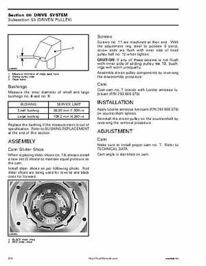
A15D0OA
1Measure thickness of slope base here 2Sliding pulley side 3Slope base
Bushings
Measure the inner diameter of small and large bushings no8 and no9BUSHING Small bushing Large bushing SERVICE LIMIT 38.30 mm (1.508 in) 108.2 mm (4.260 in)
Coat cam no7 interior with Loctite antiseize lubricant (PN 293 800 070)
INSTALLATION