2005 Ski-Doo RT Series Shop Manual, Page 167Get this manual
Section 04 ENGINE MANAGEMENT (SDI) Subsection 03 (COMPONENT INSPECTION, REPLACEMENT AND ADJUSTMENT)
Refer to TEMPERATURE SENSOR TABLE at the beginning of this section to find the corresponding resistance value for this sensor temperatureRecheck also resistance value between terminals 11 and 27 on ECM connector AThis resistance is used for ECMRefer to TEMPERATURE SENSOR TABLE at the beginning of this section to find the corresponding resistance value for this sensor temperatureIf resistance value is correct, try new ECMRefer to ENGINE CONTROL MODULE (ECM) in this sectionIf resistance value is incorrect, repair the connectors or replace the wiring harness between ECM connector and the CTS
Voltage Test
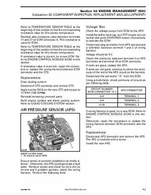
Check the voltage output from ECM to the APSInstall the tether cord cap, turn OFF engine cut-out switch and push STARTRER button momentarily to activate the ECMDisconnect plug connector from APS and connect voltmeter between terminal and of wiring harnessVoltage should be VCheck the continuity between terminal on APS connector and terminal 18 on ECM connectorIf tests are good, replace the APSIf tests are not good, continue to check the continuity of the rest of the APS circuit on the harnessDisconnect the connector "A" from the ECMUsing multimeter, check continuity of circuits as per following tableCIRCUIT NUMBER (ECM CONNECTOR "A") A-3 A-4 A-18 APS CONNECTOR TERMINAL TERMINAL TERMINAL 3