2005 Ski-Doo RT Series Shop Manual, Page 163Get this manual
Section 04 ENGINE MANAGEMENT (SDI) Subsection 03 (COMPONENT INSPECTION, REPLACEMENT AND ADJUSTMENT)
NOTE: The resistance value should change smoothly and proportionally to the throttle movementOtherwise, replace TPSIf resistance values are correct, try new ECMRefer to ENGINE CONTROL MODULE (ECM) in this sectionIf resistance values are incorrect, replace TPS
Replacement
Remove the throttle body as described aboveLoosen two screws retaining the TPSRemove TPS
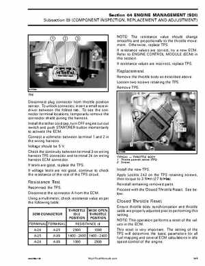
A32C9SA
Disconnect plug connector from throttle position sensorTo unlock connector, insert small screwdriver between the folded tabTo see the connector terminal locations, temporarily remove the connector shield joining the harnessInstall the tether cord cap, turn OFF engine cut-out switch and push STARTRER button momentarily to activate the ECMConnect voltmeter between terminal and in the wiring harnessVoltage should be VCheck the continuity between terminal on wiring harness TPS connector and terminal 24 on wiring harness ECM connectorIf tests are good, replace the TPSIf voltage tests are not good, continue to check the resistance of the rest of the TPS circuitA32C9RB