2002 Ski-Doo Shop Manual Volume Two, Page 202Get this manual
Section 06 ELECTRICAL Subsection 04 (TESTING PROCEDURE)
DESS Switch Wire Check continuity (null resistance) between switch center terminal and WHITEGRAY wire connectorCheck continuity (null resistance) between switch side ring and BLACKGREEN wire connectorIf readings do not correspond to the above mentioned indications, replace switchIf none of these verifications are conclusive, the problem finds its source in the main wiring harnessProceed as follows: NOTE: For the next step, no switch must be connected to the main wiring harnessDisconnect all switches from the main wiring harness and check the continuity of each wire by connecting probes to the end of wires of the same colorRepeat with all other wiresIt is important to mention that all wires of the same color within given harness are connected togetherThese wires should therefore have closed circuitOn the other hand, BLACK and BLACKYELLOW wires must have an open circuit (0.L )Repair or replace if necessary
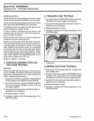
5TRIGGER COIL TESTING
1Connect probes to WHITEYELLOW and BLUE YELLOW wires from trigger coil housing2Activate the manual starter and check values indicated by the multimeter3Repeat operation times4Compare readings with those appearing in the IGNITION table