2001 Ski-Doo Factory Shop Manual Volume One, Page 270Get this manual
Section 06 ELECTRICAL Subsection 06 (TESTING PROCEDURE)
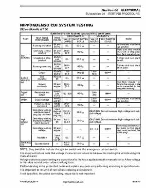
NIPPONDENSO CDI SYSTEM TESTING
593 on Skandic WT LC
IGNITION SYSTEM TESTING (Skandic WT LC 290 2001) RESISTANCE VOLTAGE TEST TO BE WIRE NOTE PERFORMED COLOR VALUE MULTIMETER VALUE MULTIMETER (OHMS) SCALE (VOLTS) SCALE BK and All switches must be in 00.0 Running insulation 0.L BKYL run positionOnly one stop switch Continuity in stop BK and 00.0 00.0 must be in stop posiposition BKYL 00.5 tionTest one at timeBKGN Insulation in stop Tether cord cap must 00.0 and 0.L position be offBKWH BKGN Tether cord cap must 00.0 00.0 Running continuity and be in place00.5 BKWH RD and 11.6 15.0 Output 00.0 00.0VAC BKRD 21.6 30.0 Coil RD and 00.0 0.L insulation BK The term "engine" refers to the engine metal Ground BK and 00.0 00.0 parts connected to the continuity engine 00.5 magneto housingWHYL Resistance and .200 00.0 and 190300 .000VAC output .350 BLYL All switches must be in WHBL 25.0 Output voltage 00.0VAC run positionand BK 100.0 Primary winding WHBL 00.0 00.0 resistance and BK 00.9 Spark Secondary winding plug cap 19.5 CAUTION: Do not measure high voltage coil out00.0 resistance (spark Spark 26.5 put voltageplug cap included) plug cap Secondary winding resistance (without spark plug cap) Secondary winding voltage Insulation Spark plug cap Cap resistance BK and BK BK and engine Spark plug cap BK 9.6 14.4 00.0 CAUTION: Do not measure high voltage coil output voltage0.11.4 0.00VAC The measurement must be taken on the spark plug wire (without the spark plug)