1997 Ski-Doo Factory Shop Manual Volume Two, Page 185Get this manual
Section 04 TRANSMISSION Sub-Section 08 (GEARBOX)
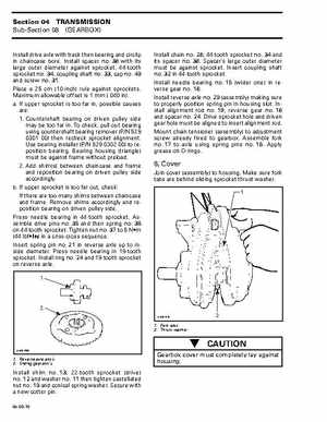
Install drive axle with track then bearing and circlip in chaincase boreInstall spacer no38 with its large outer diameter against sprocket, 44-tooth sprocket no34, coupling shaft no33, cap no40 and screw no31Place 25 cm (10-inch) rule against sprocketsMaximum allowable offset is mm (.040 in)aIf upper sprocket is too far in, possible causes are: 1Countershaft bearing on driven pulley side may be too far inTo check, pull out bearing using countershaft bearing remover (PN 529 0301 00) then recheck sprocket alignmentUse bearing installer (PN 529 0302 00) to reposition bearingBearing housing (triangle) must be against frame without preload2Add shim(s) between chaincase and frame and reposition bearing on driven pulley side accordinglybIf upper sprocket is too far out, check: If there are too many shims between chaincase and frameRemove shims accordingly and reposition bearing on driven pulley sidePress needle bearing in 44-tooth sprocketAssemble drive pins no35 and their spring no36 on 44-tooth sprocketTighten nut no37 to Nm (44 lbfin) in criss-cross sequenceInsert spring pin no21 in reverse axle up to inside diameterPress needle bearing in 19-tooth sprocketInstall ring no24 and 19-tooth sprocket on reverse axleInstall chain no28, 44-tooth sprocket no34 and its spacer no38Spacer's large outer diameter must be against sprocketInsert coupling shaft no32 in 44-tooth sprocketInstall needle bearing no15 (wider one) in reverse gear no18Install reverse axle no20 (assembly) making sure to properly position spring pin in housing slotInstall alignment rod no19, reverse gear no18 and spacer no24Drive sprocket hole and driven gear hole must be aligned to insert alignment rodMount chain tensioner (assembly) to adjustment screw already fixed to gearboxAssemble fork no17 to axle using spring pins no16Apply grease on O-rings