1989 Ski-Doo Repair Manual, Page 270Get this manual
Section 03 TRANSMISSION Sub-section 03 (DRIVE PULLEY)
Apply Loctite 242 on set screw threads, then tighten screw slightly until it rests against bottom of "Duralon" bushing hole
13,14, Innerouter half
Lock crankshaft in position as explained in removal procedureInstall inner half on crankshaft extension then position outer half assembly on inner half square shaftCAUTION: Be careful when installing outer half assembly on square shaft of drive pulley to avoid scratches on "Duralon" bushing caused by square shaft edge
5,21, Hub plugbushing
Gently grind small chamfer at one end to ease bushing assembly and push into hub plug as illustrated
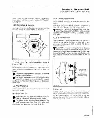
1,2,3, Governor cup
Grind chamfer
Install governor cup making sure that the shaft end rests in governor cup seatingPosition cap screw with new locking tab then torque to 85 Nm (63 Ibfft)Do not bend lock tab yetCAUTION: Incorrect seating of shaft end in govT ernor cup can cause crankshaft bendingWhen pulley is completely assembled always measure distance of both pulley halves to make sure that the pulley is properly installedDistance must be 76 mm (3 in)