1984 Ski-Doo Shop Manual, Page 261Get this manual
SECTION 03 TRANSMISSION SUB-SECTION 08 (GEARBOX)
DISASSEMBL Y
32,48, Bearings
Use the fol lowing tools and proceed as follows: Remove the bearings from the drive shaft using the following tools: hydraulic press ring halves (PIN 420 876 330) ring (PIN 420 977 480) plate (PI 420 977 700) hexagonal screws M8 25 (PIN 420 240 275)
45, Drive shaft and components
To reinstall the drive shaft components on the drive shaft, proceed as follows:Install the driven pulley shaft side bearing (PI 420 432040) on the shaft using the following suggested tool: cylindrical steel tube
Materia l: cylindrical steel tube 32 mm (1 14 ") O.D26 .8 mm (1 .055"I.D
- Insta ll the circlip over the bearingInstall the remaining componentsInstall the other shaft end bearing with shim(s) as required using the above mentioned too lAvailable shims:
25 .5 340.2 (PIN 420 944 470) 25.5 340.3 (PIN 420 944 471) 25.5 340.5 (PIN 420 944 472)
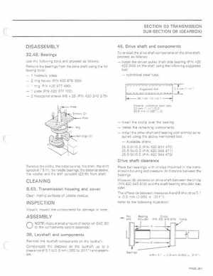
Drive shaft clearance
Remove the circlip, the distance ring, the shim, the shift sprocket (19 th)the needle bearings, the distance sleeve, the washer and the shift sprocket (23 th) from shaftPlace ball bearings with circlips mounted in the transmission housing and measure (A) distance between the bearings Measure (8) distance on drive shaft between the circlip (PIN 420 945 810) and the shaft bearing shoulder (key side)The difference between measures and should be 0.1 0.3 mm (0.003 .011 ")Refer to the following illustration