1984 Ski-Doo Shop Manual, Page 228Get this manual
SECTION 03 TRANSMISSION
SUB-SECTION 04 (DRIVEN PULLEY)
7Couer pin
2Castellated nut
3Spring washer 4Sprocket 5Bearing cone 6Chaincase 7Snap ring 8Spacer (thin) 9Chain 7OSprocket 7Spacer (thick) 72Elastic flanged stop nut M8 7.25 73Shim 74Threaded spacer 75Carriage bolt M8 7.25 55 76Brake assy 77Taptile screw M6 76 78Brake disc 79Fixed half 20Shim
27222324
3233343536373839
Shim Sliding half Bushing Spring Outer cam Slider shoe Roll pin Spacer Support Snap ring Nut Ball joint Clevis Pin Ring terminal Hair pin Wire Ring terminal Rivet Drive axle holder
REMOVAL
To remove driven pulley from vehicle, chaincase and driven pulley must be removed as an assembl yFollow this procedure :
Drive axle seal
Push towards drive axle sprocket
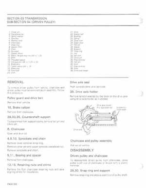
39, Drive axle holder
Remove tension exerted by the track on the drive axle using drive axle holder as illustratedDrive axle hOlder PIN529005100