1981 Ski-Doo Shop Manual Supplement, Page 113Get this manual
SECTION 05
SUB-SECTION 08 (GEARBOX
ASSEMBLY AND DISASSEMBLY
When assembling, always position new "0" ring into approp riate groove of tensioner axle) When assembling gearbox, always position new "0" ring on index rod).The gear change fork inco rporates spring loaded ballEnsure that spring and ball do not fly out during removal of index rod Gear change shaft free-play:
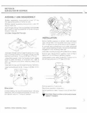
IN STALLATION
Befo re installing gearbox on veh iclecheck and adjust gear change lever Shift sprocket must ali gn co rrectly ith co rresponding gear when lever is well engagedIf requ ireduse screwdriver to turn index rod and obtain proper meshing of teethRecheck shift sp rocket engagement after adjusting index rodLock index rod using nut ith Loctite 242 on threadsInstall gear change shaft on upper housing then on outside of housingposition shim gear change lever washer and nut Torque to 23 N.m (17 ft-Ibs) Using feeler gauge, check that free-play of gear change shaft is within tolerance of 0.15-0.30 mm (,006 to .012")If free -play is not ithin tolerance, adjust using shims Install gear change lever as per following illustrationInstall washer and nut Torque to 23 Nom (17 ft Ibs)Posit ion gear change fork in gearbox cover so that it al igns with slot of sleeve in gearbox hou sing Install gearbox cover using Loctite 515 Torque nuts in the follow in sequence to 27 Nom (20 ft -Ibs)