1974 Ski-Doo Shop Manual, Page 31Get this manual
DRIVEN PULLEY, TYPE 2
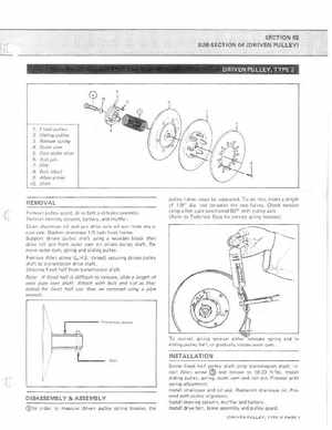
1Fixed pullev 2Sliding pulley 3Release spring 4Outer cam 5Cam slider shoe 6Roll pin 7Disc 880lt (disc) 9Allen screw 10Shim
pulley halves must be separatedTo do this, insert length of 18" diarod between the two halves Check tension using fish scale positioned 90 with pulley axle{Refer to Technical Data for correct spring tension}
REMOVAL
Remove pulley guard, drive belt and brake assemblyRemove steering column, battery, and mufflerDrain chaincase oil and pry drive axle oil seal from chaincase sideSlacken chaincase 12 inch from frameSupport driven pulley shaft using wooden block then drive roll pin from outer cam on driven pulley shaft Remove outer cam, spring and sliding pulleyRemove Allen screw {L.H.Sthread} securing driven pulley shaft to transm ission drive shaftUnscrew fixed half hom transmission shaftNote: If fixed half is difficult to remove, slide length of steel pipe over shaftA ttach with bolt and nut as illustrated;the fixed half can then be removed using pipe wrench