1970-1979 Ski-Doo Snowmobiles Service Manual, Page 88Get this manual
ENGINE 5Secure valve disc with washer and screwInstall rotary valve coverEnsure that a-ring is properly positionedInstall carburetors
4With protractor or degree wheel mark ATOC closing point from top edge of inlet port as shown in Figure 925Proceed to Step 3b of Rotary Valve InstallationCooling Fan DisassemblyAssembly This procedure requires special tool to remove fan from fan housingIf special tool or locally fabricated equivalent is not available, refer task to an authorized dealerRefer to Figure 93 for typical cooling fan assembly1Remove fan housing2Install fan holder tool to hold fan and remove fan nut (Figure 94)3Remove lockwasher with outer half of pulley, shims, inner pulley, shim, Woodruff key and fan (Figure 95)NOTE: Newer type pulley half is constructed without shoulder on the inner face (Figure 96)A 0.230 in(6mm) spacer must be installed with new style pulley half
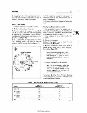
Rotary Valve Timing Refer to Table for timing specifications1Perform Rotary Valve Removal2Rotate magneto side piston to TOC (top dead center)Use dial indicator-type timing gauge as described in Chapter OneOn 354 engines, install special locking bolt to hold magneto side piston at TOC (Figure 90)3Use protractor or degree wheel and mark BTOC opening point from bottom edge of magneto side inlet port as shown in Figure 91Magneto side inlet port