Polaris 2001 High-Performance Snowmobile Service Manual (PN 9916690), Page 296Get this manual
REAR SUSPENSIONTRACKTRACTION Shock Valving Arrangement
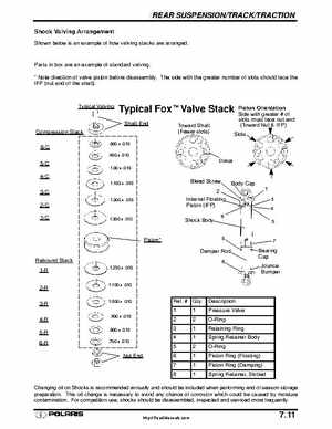
Shown below is an example of how valving stacks are arranged
Parts in box are an example of standard valving Note direction of valve piston before disassemblyThe side with the greater number of slots should face the IFP (nut end of the shaft)
Typical Valving
Typical FoxtValve Stack t
Shaft End Toward Shaft (Fewer slots)
Piston Orientation Side with greaterof slots must face nut end (Toward NutIFP)
Compression Stack 6-C 5-C
1.00 .010 .800 .010 .900 .010
Orifice
1.100 .010
Bleed Screw Internal Floating Piston (IFP) Shock Body
Body Cap
1.300 .010