2006-2008 Polaris Snowmobiles FS/FST Service Manual., Page 307Get this manual
Chassis Electrical System Checking Components
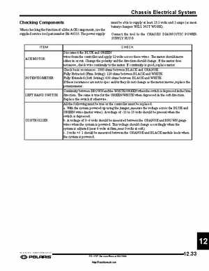
When checking the function of all the ACE components, use the supplied service tool part number PA-46355The power supply must be able to supply at least 13.1 volts and amps (as most battery chargers WILL NOT WORK)Connect the tool to the CHASSIS DIAGNOSTIC POWER SUPPLY PLUGCHECK Disconnect the BLUE and GREEN wires from the controller and apply 12 volts across these wiresThe motor should move either in or outChange the polarity and the direction should changeIf the motor does not move, check wire continuity to the motorIf continuity is good, replace motorCheck basic resistances: 1000 ohms between BLACK and ORANGEFully Retracted (Firm Setting): 120 ohms between BLACK and WHITEFully Extended (Soft Setting): 650 ohms between BLACK and WHITEIf these resistances are not to spec andor they do not change as the motor moves, replace the potentiometerContinuity between BROWN and the WHITEGREEN when the switch is depressed in the firm directionThe same is true for the GREENWHITE when depressed in the soft directionReplace the switch if otherwiseAll the following must be true or the controller must be replacedaWith the system powered up using the jumper, measure the voltage across the BLUE and GREEN wires (motor wires)A voltage of -13 to 13 volts should be present when the switch is depressedbA voltage of 06 volts should be measured between the ORANGE and BROWN gauge wires when the system is poweredThis voltage should change accordingly when the system is adjusted (near volts at firm, near volts at soft)c5 volts +- should be measured between the ORANGE and BLACK module leads when the system is powered