2004 Polaris Touring Service Manual, Page 238Get this manual
SUSPENSION Typical Shock Valving Arrangement
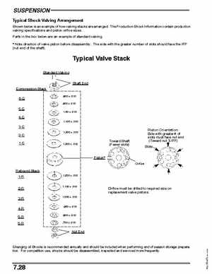
Shown below is an example of how valving stacks are arrangedThe Production Shock Information contain production valving specifications and piston orifice sizesParts in the box below are an example of standard valving Note direction of valve piston before disassemblyThe side with the greater number of slots should face the IFP (nut end of the shaft)
Typical Valve Stack
Standard Valving Shaft End Compression Stack 6-C 5-C 4-C
1.100 .010 .800 .010 .900 .010 1.00 .010
1.300 .010
1.300 .012