2003 Polaris Deep Snow Snowmobiles Service Manual, Page 274Get this manual
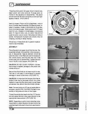
SUSPENSIONS Place the shock piston rod upper mount in bench vise, begin piston and valve removalArrange parts removed in the sequence of disassemblyThe piston should have the flat slots facing the nut end (as highlighted in black)(PICTURE 9)
Items to inspect: Piston rod for straightness, nicks or burrsCylinder Head AssemblyDU Bearing clean, inspect, or replaceInside of shock body for scratches, burrs or excessive wearTeflon piston and I.F.P wear band for cuts, chipped or nicked edges, or excessive wearOrings for nicks, cuts, or cracksCap and rod seals for nicks, cuts or cracksValve discs for kinks or wavesCompression bumpers (ski shocks only) for chipping, cracking or being missingShould any of these items be in question replacement is recommendedASSEMBLY: Place the piston rod upper mount into the viseReassemble damper rod assembly in the reverse order of disassemblySpecial attention should be paid the order of the Rebound and Compression disc (shim) stacks, ensuring that they are in the same order prior to disassemblyTighten the lock nut to 1520 ft-lb of torque(PICTURE 10) CAUTION: DO NOT OVERTORQUEIf excessive torque is applied, damage to the piston and valves will occurSecure the shock body by its lower mount in viseThe use of soft jaws is recommend to prevent damage or marks to the shock(PICTURE 11) CAUTION: It is important that the gas shock be retained in the vice by the lower mountAny other method of securing the shock body during these procedures may deform the shock body cylinderNote: The next points on IFP are not applicable for emulsion shocks (PN: 7041992) Proceed to assembly of the pressure valve on next pageThread the positioning head onto the I.F.P locator tool and adjust the top of the value indicator to the appropriate measurement(PICTURE 12) NOTE: Depending on which shock absorber is being worked on, adjust the piston location tool to the specified depth indicated in the shock specification chart