2000 Polaris Indy 500 / 600 snowmobile service manual, Page 289Get this manual
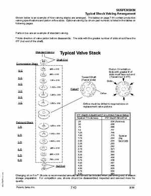
SUSPENSION Typical Shock Valving Arrangement Shown below is an example of how valving stacks are arrangedThe tables on page 7.44 contain production valving specifications and piston orifice sizesOptional valving (by shock part number) is listed in the tables on following pages
Parts in box are an example of standard valving Note direction of valve piston before disassemblyThe side with the greater number of slots should face the IFP (nut end of the shaft)
Standard Valving
Typical Valve Stack
Shaft End
Compression Stack 6-C 5-C 4-C
1.100 .010 .800 .010 .900 .010 1.00 .010
Toward Shaft (Fewer slots) Piston
Orifice
Piston Orientation Side with greaterof slots must face nut end (Toward nutIFP) Slots
1.300 .010
1.300 .012