1990-1998 Arctic Cat Snowmobiles Repair Manual, Page 254Get this manual
CHAPTER SEVEN
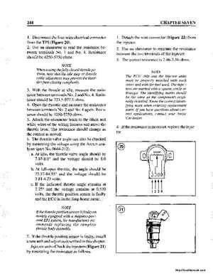
1Detach the wire connector (Figure 22) from the injector2Use an ohmmeter to measure the resistance between the two terminals of the injector3The correct resistance is 2.46-3.34 ohmsNOTE The ECU chip and the injector units must be properly matched with each other and with the fuel usedThe injectors are marked with square, circle or triangleThe identifying marks should be the same as the components originally installedKnow the correct identifying mark when ordering replacement partsIf you have questions about correct applications, contact your Arctic Cat dealer
1Disconnect the four-wire electrical connector from the TPS (Figure 20)2Use an ohmmeter to read the resistance between terminals No1 and No.4Resistance should be 4250-5750 ohmsNOTE When testing the fully closed throttle position, note that the idle stop or throttle cable adjustment may prevent the throttles from closing completely
3With the throttle at idle, measure the resistance between terminals No.2 and No.4Resistance should be 723.5-977.5 ohms4Open the throttle and measure the resistance between terminals No.2 and No.4 againResistance should be 4250-5750 ohms5Attach the ohmmeter leads to the black and white wires of the wiring harness and move the throttle leverThe resistance should change as the control is moved6The throttle valve angle can also be checked by measuring the voltage using the Arctco analyzer (part No0644-212)aAt idle, the throttle valve angle should be 7.85-8.0 and the voltage should be 8.0 voltsbAt full-open throttle, the angle should be 75.37-84.93 and the voltage should be 3.81-4.23 voltscIf the indicated throttle angle remains at 2.25 and the voltage remains at 0.570 volts, the throttle position sensor is faulty and the ECU is in the limp horne mode