1996-1998 Yamaha Factory Service Manual EXT1100U/V/W Exciter PN LIT-18616-01-53, Page 92Get this manual
JET PUMP REMOVAL AND INSTALLATION CHART
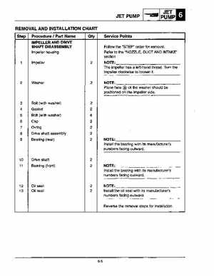
Step Procedure Part Name
IMPELLER AND DRIVE SHAFT DISASSEMBLY
Impeller housing
Service Points
Follow the "STEP" order for removalRefer to the "NOZZLE, DUCT AND INTAKE" section
Impeller
NOTE: The impeller has left-hand threadTurn the impeller clockwise to loosen it
NOTE: Plane face of the washer should be positioned on the impeller side4
Bolt (with washer) Gasket Bolt (with washer) Cap O-ring Drive shaft assembly Bearing (rear)