1996-1998 Yamaha Factory Service Manual EXT1100U/V/W Exciter PN LIT-18616-01-53, Page 79Get this manual
REMOVAL AND INSTALLATION CHART Step Procedure Part Name
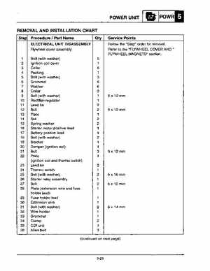
ELECTRICAL UNIT DISASSEMBLY Flywheel cover assembly
Service Points
Follow the "Step" order for removalRefer to the "FLYWHEEL COVER AND" FLYWHEEL MAGNETO" section
1 10 11 12 13 14 15 16 17 18 19 20 21 22 23 24 25 26 27 28 29 30 31 32 33 34 35 36
Bolt (with washer) Ignition coil cover Collar Packing Bolt (with washer) Grommet Washer Collar Bolt (with washer) Rectifier-regulator Lead tie Bolt Plate Nut Spring washer Starter motor positive lead Battery positive lead Bolt (with washer) Bracket Damper (ignition coil) Bolt Plate (ignition coil and thermo switch) Lead tie Thermo switCh Bolt (with washer) Starter relay assembly Bolt Plate (extension wire and fuse holder lead) Fuse holder lead Extension wire Bolt (with washer) Wire holder Grommet Clamp COl unit Allen bolt