1994-1997 Yamaha WaveRider Service Manual LIT-18616-RA-00, Page 103Get this manual
IpOWRI-1 Step 10 11 12 13 14 15 16 17 18 19 20 21 22 23 24 25 26 27 28 29 30 31 32
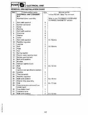
ELECTRICAL UNIT
Q'ty Service points Follow the left "Step" for removalRefer to the "FLYWHEEL COVER AND FLYWHEEL MAGNETO" section5 2
REMOVAL AND INSTALLATION CHART
ProcedurePart name ELECTRICAL UNIT DISASSEMBLY Flywheel cover assembly Bolt (with washer) Ignition coil cover Collar Packing Bolt (with washer) Grommet Washer Collar Bolt (with washer) Rectifier-regu lator Lead tie Bolt Plate Nut Spring washer Starter motor positive lead Battery positive lead Bolt (with washer) Bracket Damper (ignition coil) Bolt Plate (ignition coil and thermo switch) Lead tie Thermo switch Rectifier-regu lator Bolt (with washer) Starter relay assembly Bolt Plate (extension wire and fuse holder lead) Fuse holder lead Extension wire Bolt (with washer)