Bombardier SeaDoo 2000 factory shop manual volume 1, Page 280Get this manual
Section 08 ELECTRICAL SYSTEM Subsection 04 (STARTING SYSTEM)
STARTER REMOVAL
Disconnect BLACK cable ground connection from battery
STARTER DISASSEMBLY
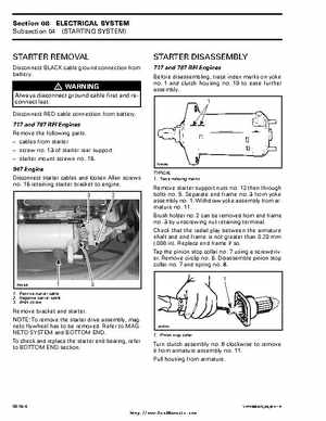
717 and 787 RFI Engines Before disassembling, trace index marks on yoke no1 and clutch housing no10 to ease further assemblyWARNING
Always disconnect ground cable first and reconnect lastDisconnect RED cable connection from battery717 and 787 RFI Engines Remove the following parts: cables from starter screw no13 of starter rear support starter mount screws no16
F01H0PA
947 Engine Disconnect starter cables and loosen Allen screws no16 retaining starter bracket to engine3 2
TYPICAL 1Trace indexing marks
Remove starter support nuts no12 then through bolts no5Separate end frame no3 from yoke assembly no1Withdraw yoke assembly from armature no11Brush holder no2 can be removed from end frame no3 by unscrewing nut retaining terminalCheck that the radial play between the armature shaft and end frame is not greater than 0.20 mm (.008 in)Replace end frame if soTap the pinion stop collar no7 using screwdriverRemove circlip no6Disassemble pinion stop collar no7 and spring no81