Bombardier SeaDoo 2000 factory shop manual volume 1, Page 71Get this manual
Subsection 03
Section 04 ENGINE (REMOVAL AND INSTALLATION)
Carefully slide shaft through support Insert shaft end into PTO flywheelNOTE: Ensure the protective hose and carbon ring (or seal carrier) is removed to check engine alignmentIf the alignment is correct, the shaft will slide easily without any deflection in PTO flywheel
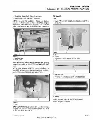
XP Model Use: plate (PN 529 035 507) for the 155.6 mm (6-18 in) jet pump
F00B0FA F07D05A
TYPICAL 1Alignment shaft 2PTO flywheel
1Plate 2Support
alignment shaft (PN 529 035 590)
If the alignment is incorrect loosen engine support screws to enable to align PTO flywheel with shaft endNOTE: Use shim(s) (PN 270 000 024 or PN 270 000 025) as necessary between engine supports and rubber mounts to correct alignment