Bombardier SeaDoo 1997 factory shop manual, Page 340Get this manual
Section 13 WIRING DIAGRAMS Sub-Section 01 (WIRING DIAGRAMS)
WIRING DIAGRAMS
WIRE COLOR CODES
First color of wire is the main colorSecond color is the tracerExample: YELLOWBLACK is YELLOW wire with BLACK tracerAMP CONNECTOR
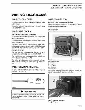
GS, GSI, GSX, GTI and XP Models These connectors are found on the MPEM of the aforementioned watercraft
Description
WIRE DIGIT CODES
GS, GSI, GSX, GTI and XP Models First number indicates in which connector the wire is plugged inSecond number indicates the position of the wire in the connectorThe letter at the end of the number (if applicable) indicates common circuit in the MPEM printed circuit with another wire bearing the same letterExample: 2-18 (g) The first number indicates that the wire is positioned in the connector no2 of the MPEMThe second number indicates that the wire is positioned in the terminal no18The letter (g) indicates common circuit with another wire(s) bearing the same letter (g) in the circuit1