2004 Polaris Freedom, Virage, Genesis and MSX-140 Service Manual., Page 275Get this manual
ELECTRICAL SYSTEMS Hall Effect Sensor Testing
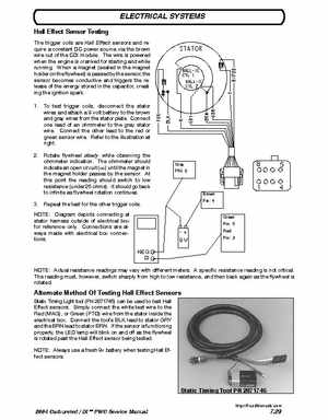
The trigger coils are Hall Effect sensors and require constant DC power source via the brown wire out of the CDI moduleThe wire is powered when the engine is cranked for starting and while runningWhen magnet (sealed in the magnet holder on the flywheel) is passed by the sensor, the sensor becomes conductive and triggers the release of the energy stored in the capacitor, creating the ignition spark1To test trigger coils, disconnect the stator wires and attach volt battery to the brown and gray wires from the stator plateConnect one lead of an ohmmeter to the gray stator wireConnect the other lead to the red or green sensor wireRefer to the illustration at right2Rotate flywheel slowly while observing the ohmmeter indicationThe ohmmeter should indicate an open circuit (1) until the magnet in the magnet holder passes by the sensorAt this point the reading should switch to low resistance (under 25 ohms)It should go back to infinite as flywheel rotation continues3Repeat the test for the other trigger coilsNOTE: Diagram depicts connecting at stator harness outside of electrical box for reference onlyConnections are always made with electrical box connectionsNEG NOTE: Actual resistance readings may vary with different metersA specific resistance reading is not criticalThe reading must, however, switch sharply from high to low resistance, and then back again as the flywheel is rotated