Yamaha Outboard Motors Factory Service Manual F6 and F8, Page 504Get this manual
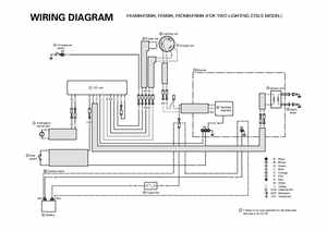
WIRING DIAGRAM 4 Oil pressure switch
F6AMHF6MH, F6BMH, F8CMHF8MH (FOR TWO LIGHTING COILS MODEL)
6 Lighting coil Pulser coil
7 Charge coil
A Bracket
1 CDI unit
9 Ignition coil
Y GW WR Br GW B
8 Rectifier regulator
10 Spark
2 Emergency signal light