Yamaha Marine Outboards F4A/F4 Factory Service Manual, Page 10Get this manual
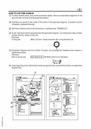
E HOW TO USE THIS MANUAL 1 To help identify parts and clarify procedure steps, there are exploded diagrams at the start of each removal and disassembly section2 Numbers are given in the order of the jobs in the exploded diagramA circled number indicates disassembly step3 Symbols indicate parts to be lubricated or replaced (see "SYMBOLS")4 job instruction chart accompanies the exploded diagram, providing the order of jobs, names of parts, notes in jobs, etcExample: O-ring size 39.5 2.5 mm: Inside diameter (D) ring diameter (d)
5 Dimension figures and the number of parts, are provided for fasteners that require tightening torque: Example: Bolt or screw size 10 25 mm (2)M10(D) 25 mm (L) (2pieces)
6 Jobs requiring more information (such as special tools and technical data) are described sequentially1 2
LOWER UNIT
EXPLODED DIAGRAM
LOWER UNIT
LOWER CASING CAP ASS'Y
SERVICE POINTS
1 16 17 15 11 13
Lower casing capPropeller shaft bearing removal 1Remove: 9Ball bearing Slide hammer set 2: YB-06096 Stopper guide plate 3: 90890-06501 Bearing puller 4: 90890-06535 Bearing puller craw 5: 90890-06537 Stopper guide stand 6: 90890-06538