2001 Edition Yamaha F225A and LF225A Outboards Service Manual, Page 214Get this manual
Lower unit
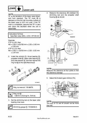
4Measure the clearance (M) between the shimming tool and the propeller shaft housing as shown
NOTE: "R" is the deviation of the lower case dimension from standardThe "R" mark is stamped on the trim tab mounting surface of the lower case in 0.01 mm unitsIf the "R" mark is unreadable, assume that "R" is zero and check the backlash when the unit is assembledCalculation formula: Specified value (M0)2.50R100 mm Example: If "R" is (+5), then M02.50(+5)100 mm2.500.05 mm2.55 mm If "R" is (3), then M02.50(3)100 mm2.50 0.03 mm2.47 mm 2Install the shim(s) 1, thrust bearing 2, propeller shaft 3, taper roller bearing 4, and claw washer 5, and then tighten the ring nut to the specified torque