1998-2006 Yamaha F20/F25 Outboards Service Manual, Page 147Get this manual
CONTROL UNIT CONTROL UNIT
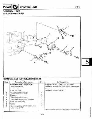
EXPLODED DIAGRAM
REMOVAL AND INSTALLATION CHART
Step ProcedurePart name CONTROL UNIT REMOVAL Throttle link rod Shift link rod Throttle control lever Spacer Throttle control cam Throttle control cam bracket Shift link rod assyCollar Start-in-gear protection device wire assy(MH) Q'ty Service points Follow the left "Step" for removalRefer to "CARBURETOR UNIT" in chapter