1998-2006 Yamaha F20/F25 Outboards Service Manual, Page 115Get this manual
IPOVVRI .ill_p_O_WER U_N_I_T_C POWER UNIT
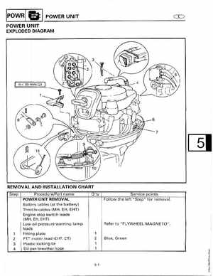
EXPLODED DIAGRAM
REMOVALIAND INSTALLATION CHART
Step ProcedurePart name POWER UNIT REMOVAL Batt1 ry cables (at the battery) Throttle cables (MH, EH, EHT) Engine stop switch leads (MM, EH, EHT) Low-ail-pressure warning lamp leads Fitting plate PTT motor lead (EHT, ET) Plastic locking tie Oil pan breather hose O'ty Service points Follow the left "Step" for removal