Suzuki outboard motors 1988 2003 repair manual., Page 240Get this manual
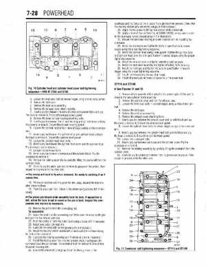
7-28 POWERHEAD crankcase and the flange of the oil seals fit snugly into their groovesCheck that the bearing stopper pins are resting snugly in their cutaways29Apply marine grease to the splined portion of the crankshaft30Apply bead of Suzuki Bond No4 (99000-31030), or equivalent sealer to the crankcase halves (shaded areas in the illustration)31Ensure the crankcase locating pins are installed prior to installing the crankcase32lnstall the crankcase and tighten the bolts to specification in several stages using the proper tightening sequence33Install the cylinder head using new gasketTighten the cylinder head and cylinder head cover bolts to specification in several stages using the proper tightening sequence34lnstall the exhaust cover and tighten attaching bolts securely35lnstall the reed valve assembly and tighten attaching bolts securely, 36Install the inlet case and tighten the bolts to specification in several stages using the proper tightening sequence37Install the thermostat cover and thermostat38Install all previously removed components to the powerhead DT115 and DT140 Fig10 Cylinder head and cylinder head cover bolt tightening sequence-1993-97 DT55 and DT65
# See Figures 11 and 2
Remove all components still attached to the powerhead until the unit is down to the bare cylinder block assembly 2Remove the silencer cover and then the silencer case3Loosen the inlet case bolts in several stages using criss-cross pattern4Remove the inlet case5Remove the reed valve assembly6Remove the exhaust cover attaching bolts7Insert pry bar between the exhaust cover and cylinder block and pry the cover to remove itDiscard the exhaust cover gasket8Loosen the cylinder head bolts in several stages using criss-cross pattern9Insert pry bar between the cylinder head and cylinder block and pry the head to remove itDiscard the cylinder head gasket10Loosen the crankcase bolts11Insert pry bar between crankcase and the cylinder blockPry the crankcase to remove it12Remove the rotating assembly by carefully lifting the crankshaft from the cylinder block13Carefully pry the piston pin retainer from its groove on the pistonThen repeat the procedure for the other side3Loosen the inlet case bolts in several stages using criss-cross pattern4Remove the inlet case5Remove the reed valve assembly6Remove the exhaust cover attachin0 bolts7Insert pry bar between the exhauit cover and cylinder block and pry the cover to remove itDiscard the exhaust cover gasket8Remove the lower oil seal housing attaching bolts9Insert pry bar between the oil seal housing and cylinder block and pry the cover to remove itDiscard the oil seal housing gasket10Loosen the cylinder head bolts in several stages using criss-cross pattern11lnsert pry bar between the cylinder head and cylinder block and pry the head to remove itDiscard the cylinder head gasket12Loosen the cylinder head cover bolts13Insert pry bar between the cylinder head cover and the cylinder head, Pry the head cover to remove it14Loosen the crankcase bolts15Insert pry bar between crankcase and the cylinder blockPry the crankcase to remove it16Remove the rotating assembly by carefully lifting the crankshaft from the cylinder block17Carefully pry the piston pin retainer from its groove on the pistonThen repeat the procedure for the other side The circlip will tend to fly when removedBe ready to catching it as it comes free18Piston pin retainers are only good for one usage, discard the retainers after removing them19Push the piston pin from it bore in the piston using brass drift if necessary The piston pin should slide smoothly from its boreIf opposition is felt, either the bore is out of round or the pin is bentInspect the components and replace as necessary20Remove the piston from the connecting rodTo assemble: 21lnstall the piston on the connecting rodMake sure the arrow on the pistons point to the exhaust port side22Push the piston pin into the piston bore using brass drift if necessary23Install new piston pin retainers, 24Lubricate the seals with marine grease prior to installation25Install the top and bottom crankshaft oil seals with the numbers facing the ends of the crankshaft26Lubricate the rotating assembly with 2-stroke oil prior to installation27Install the rotating assembly into the cylinder block, making sure the crankshaft faces the correct wayThe splined end of the crankshaft should face driveshaft housing side28Ensure the crankshaft C-rings are fitted into their grooves in the