Suzuki outboard motors 1988 2003 repair manual., Page 150Get this manual
5-38 IGNITION AND ELECTRICAL SYSTEMS 3Connect test light between the yellow and white leads and then reverse the test light leadsThe light should light up when tested in one direction and not the other4Test the red and white, black and red, and yellow and black rectifier leads, 5If the test liaht does not liaht as described in anv one of the diode directions, the rectifier must be replacednator producesVoltage is maintained at about 13.5-15 voltsDuring high engine speeds and low current demands, the regulator will adjust the voltage of the alternator field to lower the alternator output voltageConversely, when the engine is idling and the current demands may be high, the regulator will increase field voltage, increasing the output of the alternatorTESTING
1Make sure that the battery is fully charged2Remove the engine cover3Connect tachometer according to the manufacturers instructions4Start the engine and let it warm up to normal operating temperature5Connect voltmeter across the battery terminals6Slowly increase engine speed to approximately 5,000 rpmNote the voltmeter reading, if it is not 14-15 volts, the voltage regulator must be replacedREMOVALINSTALLATION
1Disconnect the negative battery cable2Disconnect the rectifier or voltage regulatorlrectifier connectors3Remove the fastener attaching the unit to the engine or electrical component and remove the unit4If so equipped, remove the ground lead and disconnect it from the powerheadTo install: 5Install the rectifier or voltage regulatorlrectifier onto the powerhead or electrical component6Connect all leads and make sure all connections are tight and free of corrosion7Connect the negative battery cableREMOVALINSTALLATION
1Disconnect the negative battery cable2Disconnect the voltage regulator connections3Remove fasteners holding the voltage regulator to the powerhead or electrical component and remove the regulator4If equipped, remove the ground wire and fastenerTo install: 5Install the regulator onto the powerhead or electrical component and tinhten the fastenertsl -a-6If equipped, reattach the ground wire and fastener7Connect the regulator leads, making sure that they are all tight and free of corrosion8Connect the negative battery cable
DESCRIPTIONOPERATION
The voltage regulator controls the alternators field voltage by grounding one end of the field windings very rapidlyThe frequency varies according to current demand the more the field is grounded, the more voltage and current the alter-I'
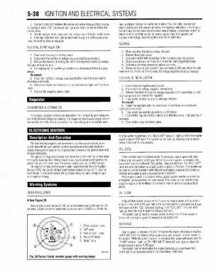
llThe fuel injected engines use an electronic ignition system which, when combined with the fuel injection system, becomes an integrated electronic engine management system that improves fuel consumption, performance and exhaust emissionsThe ignition timing control system controls the ignition timing by first determining the basic ignition timing based on an engine speed signal sent by the pulser coil and the intake manifold vacuum signal sent by the MAP sensorThe ignition timing control system, with inputs from the Throttle Position Sensor (TPS), the Engine Temperature Compensation Sensor (ECT), and the Suction Air Temperature Sensor (IAT), compensates the base timing for optimum ignition timingcaution system is act vaiea, !he "REV LIMIT" amp IN; I'gnt when me eigineao0.e 2750 rvnTne sbstem car be reset 01 rea-c'ng e'lg'ne spccd is below 2,500 rpm for one-secondOIL LEVEL