Suzuki outboard motors 1988 2003 repair manual., Page 140Get this manual
IGNITION AND ELECTRICAL SYSTEMS 4Unbolt the ignition coils and remove them from the electric parts holderTo install: 5Install the ignition coils in the electric parts holderMake sure all ground connections are in place and the retaining bolts are tight6Connect the ignition coil leads to the CDI unitMake sure all the connections are tight and free of corrosion7Install the cover on the electric parts holder8Install the spark plug wires9Install the engine coverMain switches, engine stop switches, and the like are usually connected on the wire in between the CD1 box and the ignition coilWhen the main switch or stop switch is turned to the bOFFb position, the switch is closedThis closed switch short-circuits the charge coil current to ground rather than sending it through the CDI boxWith no charge coil current through the CDI box, there is no spark and the engine stops or, if the engine is not running, no spark is producedTESTING
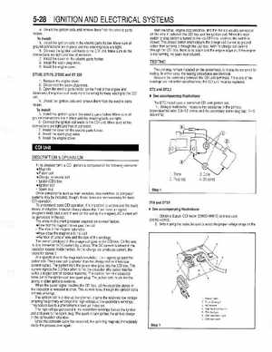
The unit may remain installed on the powerhead, or it may be removed for testingIn either case, the testing procedures are identicalMeasure the continuity between the CDI unit terminalsIf the any of the readings are not within specifications, the CDI unit must be replacedDT2 and DT2.2
DT150, DT175, DT200 and DT 225 1Remove the engine cover2Disconnect the spark plug wires3Open the electric parts holder on the front of the engine and disconnect the ignition coil leads from the wiring harness leading to the CDI unit4Unbolt the ignition coils and remove them from the electric parts holderTo install: 5Install the ignition coils in the electric parts holderMake sure all ground connections are in place and the retaining bolts are tight6Connect the ignition coil leads to the CDI unitMake sure all the connections are tight and free of corrosion7Install the cover on the electric parts holder8Install the spark plug wires9Install the engine cover See accompanying illustrations
The DT2 model uses combined CDI uniffignition coil1Using multi-meter, measure the resistance in the primary (core-bluelred wire: 0.8-1.2 ohms) and the secondary (core-plug cap: 7-1 .kilo-ohms)
DESCRIPTIONOPERATION
In its simplest form, CDI ignition is composed of the following elements: Magneto Pulser coil Charge, or source coil Igniter (CDI) box Ignition coil Spark plug Other components such as main switches, stop switches, or computer systems may be included, though, these items are not necessary for basic CDI operationTo understand basic CDI operation, it is important to understand the basic theory of inductionInduction theory states that if we move magnet (magnetic field) past coil of wire (or the coil by the magnet), AC current will be generated in the coilThe amount of current produced depends on several factors: How fast the magnet moves past the coil The size of the magnet (strength) How close the magnet is to the coil Number of turns of wire and the size of the windings The current produced in the charge coil goes to the CDI boxOn the way in, it is converted to DC current by diodeThis DC current is stored in the capacitor located inside the boxAs the charge coil produces current, the capacitor stores itAt specific time in the magneto's revolution, the magnets go past the pulser coilThe pulser coil is smaller than the charge coil so it has less current outputThe current from the pulser also goes into the CDI boxThis current signals the CDI box when to fire the capacitor (the pulser may be called trigger coil for obvious reasons)The current from the capacitor flows out to the ignition coil and spark plugThe pulser acts much like the points in older ignitions systemsWhen the pulser signal reaches the CDI box, all the electricity stored in the capacitor is released at onceThis current flows through the ignition coil's primary windingsThe ignition coil is step-up transformerIt turns the relatively low voltage entering the primary windings into high voltage at the secondary windingsThis occurs due to phenomena known as inductionThe high voltage generated in the secondary windings leaves the ignition coil and goes to the spark plugThe spark in turn ignites the air-fuel charge in the combustion chamberOnce the complete cycle has occurred, the spinning magneto immediately starts the process over again2Plug cap