Suzuki outboard motors 1988 2003 repair manual., Page 132Get this manual
5-20 IGNITION AND ELECTRICAL SYSTEMS6On the battery charging coils, measure the resistance on No.1 between the yellowlred and yellowlred wires and on No.2 between the red and yellow wiresResistance should measure between 0.1-0.3 ohms7On the condenser charging coils, measure the resistance on No.1 between the blacWred and green wires and on No.2 between blacured and brown wiresResistance should measure between 170-250 ohms8On the gear counting coil, measure the resistance between the orangelgreen and black wiresThe resistance should measure between 170-250 ohms9If the resistance reading is not within specification, replace the faulty coilDT150, DT175, DT200 and DT225 Vernier calipers
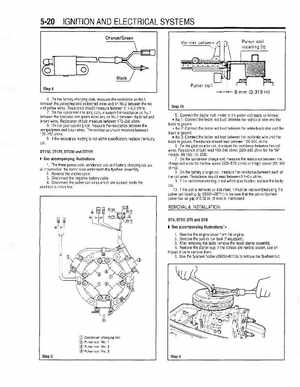
Pulser coil locating jig
See accompanying illustrations
1The three pulser coils, condenser coil and battery charging coil are all mounted on the stator base underneath the flywheel assembly2Remove the engine cover 3Disconnect the negative battery cable Disconnect the pulser coil wires which are located inside the electrical junction box+ Black
mrn (0.315 in)