Suzuki outboard motors 1988 2003 repair manual., Page 131Get this manual
IGNITION AND ELECTRICAL SYSTEMS 5-19 No.3: Connect the tester red lead between the redlwhite wire and ground No.4: Connect the tester red lead between the whitelgreen wire and ground 6Resistance should read between 160-230 ohms7On the condenser charaina coilmeasure the resistance between the blacklred and green wiresesistance should read 180-270 ohms8On the gear counting coil, measure the resistance between the orangelgreen and blacklgreen wiresResistance should measure between 160-230 ohms9On the battery charging coil, measure the resistance on both coils between the red and yellow wiresResistance should measure between 0.4-0.06 ohms10If the resistance reading is not within specification, replace the faulty coilDT115 and DT140
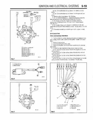
See accompanying illustrations
The four pulser coils, battery charging coil, condenser charging coil and gear counting coil are located, underneath the flywheel, mounted on the stator base,2Remove the engine cover3Disconnect the negative battery cable4Disconnect the pulser coil wires which are located inside the electrical junction box5Connect the digital multimeter to the pulser coil leads as follows: No.1: Connect the tester red lead between the redlgreen wire and the black ground wire No.2: Connect the tester red lead between the whitelblack wire and black ground wire No.3: Connect the tester red lead between the redlwhite wire and the black ground wire No.4: Connect the tester red lead between the whiteloreen wire and the black ground wireResistance should read between 170-250 ohms