Suzuki outboard motors 1988 2003 repair manual., Page 128Get this manual
5-16 IGNITION AND ELECTRICAL SYSTEMS DT25 and DT30
See accompanying illustrations
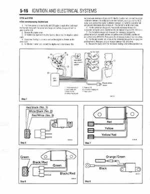
The three pulser coils are located at 120°angle to each other underneath the flywheel along with the condenser charge coil, battery charge coil and the gear counting coil2Remove the enine cover3On models equipped with electric starters, disconnect the negative battery cable4Disconnect the 6-pin connector and set the digital multimeter on the ohms scale5For the No.1 pulser coil, connect the digital multimeter between the
redlblack wire terminal and groundFor the No.2 pulser coil, connect the digital multimeter between the whitelblack wire terminal and ground and for the No.3 pulser coil, connect the digital multimeter between the redlwhite wire terminal and groundResistance should measure 170-250 ohms on the multimeter6For the condenser charge coil, measure the resistance between the blacklgreen and green wiresResistance should measure between 170-250 ohms7For the battery charge coil, measure the resistance between the yellowlred and yellow wires and red and yellow wires (DT30MC) and the red and yellow wires (DT30CR)Resistance should measure between 0.2-0.6 ohms8For the gear counter coil, measure the resistance between the orangelgreen and black wiresResistance should measure between 160-240 ohms9Replace the faulty coil if the resistance reading is not within specificationThrottle valve sensor 2Gear counter coil 3Pulser coil 4Battery charging coil