Suzuki outboard motors 1988 2003 repair manual., Page 127Get this manual
IGNITION AND ELECTRICAL SYSTEMS 5-15 The battery charging system is made up of charge coil(s) or an AC lighting coil on some modelsThe permanent magnets located on the flywheel edge, rectifier (voltage regulatorlrectifier on some models), battery and the associated wiring and fusesRotation of the flywheel magnets past the charge coil or AC lighting coils will create alternating currentThis current is then sent to the rectifier or voltage regulatorlrectifier, where it is then converted to direct current and then supplied to the battery or electrical accessories through fuseThe capacitor charge coil supplies electricity to the CDI unitAs the flywheel rotates past the capacitor charge coil, alternating current is producedThis voltage is supplied to the CDI unit and passes through diode where it is rectified to direct currentThis DIC voltage is then stored in the capacitorThe gear counter coil (if equipped) is the same construction and operation as the pulser coil, but it uses each ring gear tooth as pulsar bar to generate signal voltage to send to the CDI unit 4To test the lighting coil, connect the digital multimeter between the yellow and red wiresResistance should read between 0.1-0.2 ohms for the DT4 and DT5Y and 0.37-0.45 ohms for the DT6 and DT85If the resistance reading is not within specification, replace the faulty coilDT9.9 and DT15
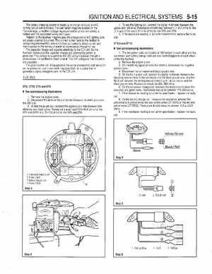
See accompanying illustrations
1The two pulser coils are located at 180°angleto each other and the condenser and battery charge coils are also located opposite of each other under the flywheel2Remove the engine cover3On models equipped with electric starters, disconnect the negative battery cable4Disconnect the connector and black ground wire5On the No.1 pulser coil, connect the digital multimeter between the blacklred wire terminal in the connector and the black ground wireAnd the No.2 coil between the whitelgreen wire terminal in the connector and the black ground wireResistance should be 260-380 ohms6On the condenser charge coil, measure the resistance between the blacklred and green wiresResistance should be between 170-250 ohms7If the resistance reading is not within specification, replace the faulty coil8On the battery charge coil, measure the resistance between the yellowlred and yellow wires, red and yellow wires (DT15MC) or the red and yellow wires (DT15CE)Resistance should measure between 0.2 and 0.5 ohms9If the resistance reading is not within specification, replace the faulty coilTESTING