Suzuki outboard motors 1988 2003 repair manual., Page 124Get this manual
5-12 IGNITION AND ELECTRICAL SYSTEMS Once the complete cycle has occurred, the spinning magneto immediately starts the process over againMain switches, engine stop switches, and the like are usually connected on the wire in between the CDI box and the ignition coilWhen the main switch or stop switch is turned to the OFF position, the switch is closedThis closed switch short-circuits the charge coil current to ground rather than sending it through the CDI boxWith no charge coil current through the CDI box, there is no spark and the engine stops or, if the engine is not running, no spark is producedreason, metal (brass) is cast in the spigot joint of the oil seal housing and stator baseParts of the stator base include coil which charges capacitor of the CDI unit, pulser coil which sends signal to the CDI unit at ignition timing, and lighting coil which generates lighting output of 12V and SOW DT9.9 and DT15
SUZUKI PEI IGNITION
The Suzuki PEI (Pointless Electronic Ignition) is magneto CDI type system DT4 and DT5Y
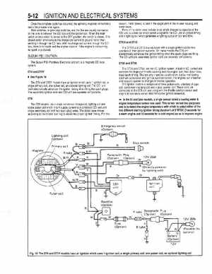
The DT9.9 and DT15 are equipped with single ignition coil for two cylinders in their ignition systemsOn these models the CDI unit electronically advances the ignition timing when the spark plugs are firingThe CDI unit and secondary ignition coils are separate components DT25 and DT30
See Figure 18
The DT4 and DT5Y models have an ignition which uses ignition coil, single primary coil, one pulser coil, an optional lighting coilThe CDI unit itself electronically advances the ignition timing when firing the spark plugsThe secondary ignition coils and CDI unit are separate componentsThe DT25 and DT30 use the I.Cignition systemA built in I.Ccontrol unit monitors the degree of throttle opening and the engine rpm, then determines ideal spark timingThis not only improves acceleration, but by maintaining optimum carburetion and ignition synchronization, the engines run smoother and respond quicker to changes in throttle operationThe ignition system is comprised of three pulser coils, battery charge coil, condenser charging coil and gear counter coilThese coils are connected to the CDI unit and along with the throttle position sensor and engine temperature sensor determines the ignition sequence In the 91 and later models, single sensor called cooling waterengine temperature sensor was usedThis sensor served two purposes: one is to detect the engine temperature with which to select either of the two different starting ignition timing duration's at 5OBTDC (3 seconds for warm engine and 15 seconds for cold engine) so as to improve engine