Suzuki outboard motors 1988 2003 repair manual., Page 123Get this manual
IGNITION AND ELECTRICAL SYSTEMS 5-11 TESTING 1Remove the flywheel2For coil primary resistance: aDisconnect the black primary ignition coil lead at the connectorbDisconnect the secondary coil lead (spark plug wire) at the spark plugcMake sure the ohmmeter is on the low-ohm scaleConnect the meter between the primary coil lead and an engine grounddCheck the resistance reading in the "Ignition Coil Resistance" chart3For coil secondary resistance: aMake sure the ohmmeter is on the high-ohms scalebConnect the meter between the secondary coil lead and an engine groundcCheck the resistance reading in the "Ignition Coil Resistance" chart4Replace the ignition coil if the either the primary or secondary resistance does not meet specificationsREMOVALINSTALLATION Remove the engine cover Remove the fuel tank assembly Remove the recoil starter assembly Remove the starter cup and magneto insulator With flywheel holder or commonly available strap wrench, hold the flywheel and loosen the retaining nut With the flywheel rotor remover (09930-30713) remove the flywheelMake sure to keep track of the flywheel key when removing the flywheel7Disconnect the plug cap and the two lead wires (that are coming from the stator) and remove the stator8Remove the stator base screw which holds the breaker point assembly to the base9Disconnect the coil and condenser leads at the breaker pointNow remove the breaker point assembly10Remove the condenser from the stator base by removing the screw To install:
11Install the replacement breaker point set on the stator baseMake sure the pivot point on the bottom of the point set engages the hole in the stator baseNow, install, but don't tighten the retaining screw12Install the condenser on the stator base and now tighten the retaining screw securely13Reconnect the stator leadsInspect the connectors and clean off any corrosion before connecting14Check the lubrication felt for drynessIf it dry, add couple of drops of 30w engine oil15Reconnect the spark plug lead Before installing the flywheel, thoroughly inspect the crankshaft and flywheel tapersThese surfaces must be absolutely clean and free of oil, grease and dirtUse solvent and lint free cloth to clean the surfaces and then blow dry with compressed air16Install the flywheel key, starter cup and flywheel and flywheel boltTighten the bolt to 30-36 ftIbs(40-50 Nm 17Install the fuel and engine cover18Remove the spark plug caps 19With an ohmmeter, measure the resistance between the spark plug wiresResistance should measure 6.4K-9.6K ohms20Measure the resistance between the primary terminal and the coil mounting lug (for ground)21Resistance should measure 0.46-0.66 ohmsSINGLE-CYLINDER IGNITION
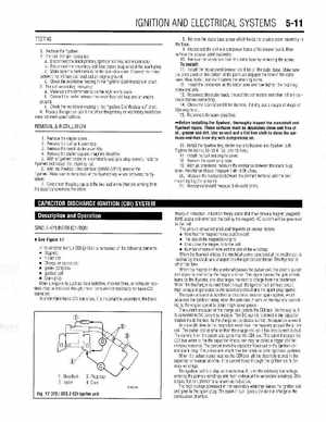
See Figure 17
In its simplest form, CDI ignition is composed of the following elements Magneto Pulser coil Charge, or source coil Igniter (CDI) box Ignition coil Spark plug Other components such as main switches, stop switches, or computer systems may be included, though, these items are not necessary for basic CDI operation To understand basic CDI operation, it is important to understand the basic