Suzuki outboard motors 1988 2003 repair manual., Page 114Get this manual
5-2 IGNITION AND ELECTRICAL SYSTEMS The actual flow of electricity depends not only on voltage and amperage, but also on the resistance of the circuitThe higher the resistance, the higher the force necessary to push the current through the circuitThe standard unit for measuring resistance is an ohm (Q).Resistance in circuit varies depending on the amount and type of components used in the circuitThe main factors which determine resistance are: Material-some materials have more resistance than othersThose with high resistance are said to be insulatorsRubber materials (or rubber-like plastics) are some of the most common insulators used, as they have very high resistance to electricityVery low resistance materials are said to be conductorsCopper wire is among the best conductors, Silver is actually superior conductor to copper and is used in some relay contacts, but its high cost prohibits its use as common wiringMost marine wiring is made of copperSize-the larger the wire size being used, the less resistance the wire will have, This is why components which use large amounts of electricity usually have large wires supplying current to themLength-for given thickness of wire, the longer the wire, the greater the resistanceThe shorter the wire, the less the resistanceWhen determining the proper wire for circuit, both size and length must be considered to design circuit that can handle the current needs of the componentTemperature-with many materials, the higher the temperature, the greater the resistance (positive temperature coefficient)Some materials exhibit the opposite trait of lower resistance with higher temperatures (negative temperature coefficient)These principles are used in many of the sensors on the engine,
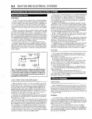
# See Figure 1
For any 12 volt, negative ground, electrical system to operate, the electricity must travel in complete circuit This simply means that current (power) from the positive termlnal (t)of the battery must eventually return to the negative terminal (-1 of the battery Along the way, this current will travel through wires fuses, switches and components If, for any reason, the flow of current through the circuit IS interrupted, the component fed by that circuit will cease to function properly Perhaps the easiest way to vsualzecircuit IS to think of connecting light bulb (wlth two wires attached to it) to the battery-one wire attached to the negative (-1 terminal of the battery and the other wire to the positive (t)terminal With the two wires touching the battery terminals, the circuit would be complete and the light bulb would IlumlnateElectricity would follow path from the batlonger wires on tery to the bulb and back to the battery It's easy to see thatour light bulb, it could be mounted anywhere Further, one wire could be fitted with switch so that the light could be turned on and off The normal marine circuit dffers fromsimple example in two ways First, Instead of having return wire from each bulb to the battery, the current travels through slngle ground wire which handles all the grounds for specific clrcult Secondly, most marine circuits contain multiple components which receive power from single circuit This lessens the amount of wire needed to power components
OHM'S LAW
There is direct relationship between current, voltage and resistanceThe relationship between current, voltage and resistance can be summed up by statement known as Ohm's lawVoltage (E) is equal to amperage (I) times resistance (R): E=l Other forms of the formula are R=El and l=ER In each of these formulas, is the voltage in volts, is the current in amps and is the resistance in ohmsThe basic point to remember is that as the resistance of circuit goes up, the amount of current that flows in the circuit will go down, if voltage remains the sameThe amount of work that the electricity can perform is expressed as powerThe unit of power is the watt (w), The relationship between power, voltage and current is expressed as: Power (W) is equal to amperage (I) times voltage (E): W=l This is only true for direct current (DC) circuits; The alternating current formula is tad different, but since the electrical circuits in most vessels are DC type, we need not get into AC circuit theory,