Suzuki outboard motors 1988 2003 repair manual., Page 107Get this manual
FUEL SYSTEM 4-45 3Turn the ignition switch to the ON position, then check the voltage (V2) to see if it matches that specified for the TVS power supply (Vl)Refer to the TVS voltage specificationsSince V1 voltage is not adjustable, reading of 3.64-4.39 volts can be considered correctIf the voltage is not between these numbers, it may indicate either fault in the ICU or short circuit of the TVS (although that is relatively uncommon occurrence)Both components therefore must be replaced and checked sequentially4If the voltage (V2) not correct, loosen the TVS set screws and gently rotate the TVS until the voltage indicated matches that specified in the chartThen retighten the set screws using thread locking compound5With the test cord still attached, reattach the emergency switch lock plate and start the engine, letting it warm up thoroughly6When the engine is at operating temperature, adjust the throttle stop screwIdle speed should be as specified in the "Tune-up Specifications" chart7Securely lock the throttle stop screw with the nutThe idle speed has been correctly adjusted, check the TVS output voltageThe reading must be lower than an upper limit referred to as maxV max is designated value at throttle opening of and when adjusting the in-gear idle speed, the throttle opening should be 4Oat most Value max corresponds directly to (and is listed alongside) interrelated V1 and V2Having checked V1 and V2 according to the TVS voltage chartV max is the third relevant throttle valve factorIf V2 and max are accurate, and within specification respectively, and if in-gear idle speed is as specified in the "Tune-Up Specifications" chart, the TVS is adjusted correctlyDESCRIPTIONOPERATION
The pulser coil is located under the flywheel rotorVoltage pulses induced in the coil by the passing reluctor bar which is attached to the flywheel rotor are signals used by the ECU to determine crankshaft angleThis is the base information from which the ECU computes the ignition spark signal in the correctly sequenced firing orderFuel injection timing is then set by this ignition signalTESTING
Pulser coil testing is covered in detail in the in "Ignition and Electrical"
DESCRIPTIONOPERATION
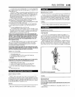
See Figure 85
The fuel injector is an electromagnet fuel injection valve operated by the injection signal supplied by the fuel injection control unitThe coil used in the injector is high pressure resistant typeThe fuel injection control unit determines the optimal fuel injection time duration on the basis of the signal input from the various sensors mounted on the engine, When the injection signal is sent to the fuel injector, it energizes the coil and pulls up the needle valve, thereby opening the valve and injecting fuelBecause fuel pressure (pressure differential between fuel line and manifold) is kept constant, the amount of fuel injected is determined by the duration time of the open8If the output voltage exceeding max is required to obtain the specified idle speed, then this abnormally wide throttle valve opening may indicate mechanical, fuel delivery or other electrical system problemsSuch circumstances should be investigated immediately If the above situation occurs when TVS input voltage) and output voltage at fully closed throttle (V2) are known to be correct, then the ICU and TVS are operating correctly and should not be checkedREMOVALINSTALLATION