Suzuki outboard motors 1988 2003 repair manual., Page 104Get this manual
4-42 FUELSYSTEM 5Connect the multimeter positive lead (red) to the light greenlred test cord lead and the tester negative lead to the test cord black leadThis voltage is referred to as V3The difference of the voltage, V2 minus V3 must be within +0.000.01 volts If the only difference between the V2 and V3 measurements is not specified, it will be necessary to perform the following adjustment procedurerotate the TVS until the voltage indicated matches that specified in the chartThen retighten the set screws using thread locking compoundDT150 AND DT200 The following special tools must be obtained to perform the sensor check: 12-pin connector test cord (09930-89940) 1Loosen the locknut and unscrew the idle adjusting screw until it is fully backed out and not touching the throttle lever Manually flock the throttle valve open and closed 2-3 times by hand, allowing the spring tension to snap the valve fully closedADJUSTMENT
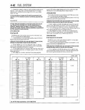
Proper idling and acceleration are dependent on the correct V2 voltageBecause of the sensitivity of V2, even the slightest amount of movement, fastening screws too tightly or securing screws unevenly may alter this readingTherefore, following installation or adjustment of the TVS, recheck V2 to ensure accuracyDT115 AND DT140
ISee Figure 80
The following special tools must be obtained to perform the sensor check 4-pin connector test cord (09930-89240) Loosen the locknut and unscrew the idle adjusting screw until it is fully backed out and not touching the throttle lever
-Manually flock the throttle valve open and closed 2-3 times by hand, allowing the spring tension to snap the valve fully closed2Set the multimeter on the DC volts setting and connect the 12-pin test cord as follows: tester positive probe (red) to the test cord orangelyellow lead and the tester negative probe (black) to the test cord light greenlblack lead3Turn the ignition switch to the ON position, then check the voltage (V2) to see if it matches that specified for the TVS power supply (VI)4If the voltage (V2) not correct, loosen the TVS set screws and gently rotate the TVS until the voltage indicated matches that specified in the chartThen retighten the set screws using thread locking compoundDT200 AND DT225