Suzuki outboard motors 1988 2003 repair manual., Page 98Get this manual
4-36 FUEL SYSTEM based on the map control in relation to engine speed, throttle valve opening angle and cylinder wall temperature2Normal operating modeThree minutes after starting, the ECU changes to the "Normal operating mode"This mode is based on the map control in relation to engine speed, throttle valve opening angle, cylinder wall temperature, air temperature and atmospheric pressure3Fail safe modeEach sensor has an assigned default value programmed into the ECUIn the event of sensor failure, the monitor gauge will flash code indicating the failure and the engine will continue to operate, but with reduced performanceInjection duration during sensor failure automatically defaults to the following control methods: Throttle valve sensor failure: Injection duration will be automatically set according to engine speedCylinder wall temperature sensor failure: injection duration will be automatically set if the sensor senses 30° Air temperature sensor failure: Injection duration will be automatically set if the sensor senses 20° Atmospheric pressure sensor failure: Injection duration will be automatically set if the sensor senses 763 mm Hg (101.7 kPa) If either the gear counter coil or the pulser coil fails, the ECU will not provide and injection signal without reference from these coilsUnder this condition, the engine can be cranked but it will not start due to no fuel being injected Fuel Delivery System
of this unit is to separate the vapor from the fuel delivered by the low pressure fuel pump, or fuel that has returned from the pressure regulatorThis vapor is 'bled" to the throttle body through the hose on the top of the vapor separatorOIL INJECTION The separator also functions as the mixing chamber for oil and fuelOil is injected into the separator tank by the engine-driven oil pumpThe amount of oil delivered to the separator tank is dependent upon engine RPM and throttle openingThe supply side of the oil injection system is similar to previous models Air Intake System
ISee Figure 72
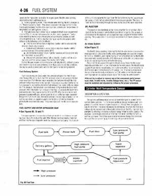
The throttle body assembly including the throttle valve sensor, is precisionmade part which detects the throttle valve opening angle and supplies signal to the ECUTherefore, when replacing any of the components within the throttle body assembly, special care should be taken so as not to alter the precise clearances and operating efficiency of the throttle bodyThe air which ahs passed through the throttle body, flows into the surge tanklintake manifold and is then distributed to the reed valvesThe throttle body adjusts the air intake amount using the throttle valve which is connected to the throttle lever and Throttle Position (TP) sensorThe TP sensor is installed on the top of the throttle body and informs the ECM of the current throttle valve opening angle and is used as basic signal for the engine control system Do not try to adjust or remove any of the component parts (sensor base plate, throttle valve, throttle linkage lever, etcThe TP sensor must be installed and adjusted by following the proper procedureFuel injectors require clean, water-free, pressurized gasolineFuel is supplied through the primer bulb, fuel filter and low pressure fuel pump to the fuel vapor separator, From the fuel vapor separator, the fuel goes through the high pressure fuel pump and on to the fuel railThe pressure regulator maintains the fuel pressure in the feed line, from the high pressure fuel pump to the fuel injectorThis pressure, maintained at constant level, is higher than the barometric pressureWhen the higher fuel pressure in the feed line exceeds the barometric pressure by more than approximately 36.3 psi (255 kPa), the valve in the fuel pressure regulator will open, allowing fuel to return to the fuel vapor separator through the fuel return hoseThe fuel is injected into the intake manifold by the fuel injector when the signal is supplied by the ECUOil mixing is accomplished with standard oil pumpThis pump injects oil into the vapor separator tankDESCRIPTIONOPERATION