Suzuki outboard motors 1988 2003 repair manual., Page 75Get this manual
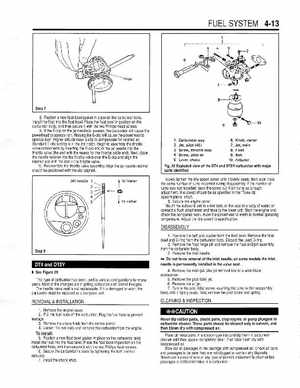
FUEL SYSTEM 4-13 8Position new float bowl gasket in place on the carburetor bodyInstall the float into the float bowlPlace the float bowl in position on the head screwscarburetor body, and then secure it with the two Phillis 9If the E-clip on the jet needle is lowered, the carburetor will cause the powerhead to operate richRaising the E-clip will cause the powerhead to operate leanHigher altitude raise E-clip to compensate for rarefied airStandard E-clip setting is in the 3rd notchBegin to assemble the throttle valve components by inserting the E-clip end of the jet needle into the throttle valve (the end with the recess for the throttle cable end)Next, place the needle retainer into the throttle valve over the E-clip and align the retainer slot with the slot in the throttle valve10Reassemble the throttle valve assemblvAlian the let needle retainershould be positioned with the slot aligned12345Carburetor assy Jet, pilot (45) Screw, throttle stop Screw, pilot air Lever, choke
6Knob, starter 7Jet, main Float 9Bolt 10Adjuster
Fig29 Exploded view of the DT4 and DT5Y carburetor with major parts identified Slowlv tiahten the idle soeed screw until it barelv seatsthen back it out the same number of turns recorded during disassemblylithe number of turns was not recorded, back the screw out 1-314 turns as rough adjustmentIdle speed should be as specified in the "Tune-up Specifications" chart8Secure the engine coverMount the outboard unit in test tank, or the boat in body of water, or connect flush attachment and hose to the lower unitStart the enaine and check the completed workAllow the powerhead to warm to normaloperating temperatureAdjust the idle speed to specificationJet needle
DISASSEMBLY