Suzuki outboard motors 1988 2003 repair manual., Page 48Get this manual
3-32 MAINTENANCE IDLE SPEED
1Warm up the engine for approximately five minutes2On the carburetor, turn the pilot screw in all the way until it lightly seats, and then back it out the number of turns specified in the "Idle Air Screw Specifications" chart3Place the remote control in forward gear, first notch4Turn the idle adjusting switch to maintain the minimum idle speed specified in the "Tune-up Specifications" chart All models from 1991 have had the "Idle Speed Adjustment Switch" removed and instead an ignition timing resistor has been installedWith this modification, the in gear idle timing with the throttle fully returned is kept at constant 6'ATDC and the in-gear idle speed is now adjusted by the throttle stop screw on the #4 carburetorcurve is cancelled and ignition timing is returned automatically to the timing of the "Idle Speed Adjustment Switch"This guarantees that the engine speed will return to idle automaticallyIf this switch does not function properly, the engine rpm will take longer to return to idle speedCARBURETOR LINKAGE
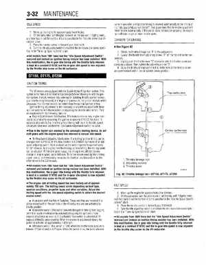
See Figure 82
1Check the throttle linkage rod "1" to the carburetors 2Loosen the throttle lever adjusting screws "2" on the top and center carburetors3Lightly push the throttle lever "3" clockwise until the throttle valves are completely closedThen tighten the adjusting screws "2"4Move the throttle linkage and check to make sure all the throttle valves are synchronized and in the completely closed positionIGNITION TIMING
The V6 models are equipped with the Suzuki digital 1C ignition systemThis system eliminates direct mechanical linkage between the engine end the ignition systemInstead, sensors relay information detailing throttle position sensor, gear counter (engine speed) and engine temperature to the ignition module which processes this information and then determines the optimal ignition timingIgnition timing adjustment is not necessary on models equipped with these ignition systems with the exception of adjusting the throttle valve sensorThey are equipped with the following features: Engine Start Advance MechanismThis feature ensures easy engine starting by automatically advancing the ignition advance to 5OBTDC for about 15 seconds, after which, the time the ignition timing will return to the idle speed circuit and what ever position the "Idle Speed Adjustment Switch" is set at Due to the higher rpm created by the automatic starting device, do not shift gears until the engine speed has returned to normal idle speedTrolling Speed Adjusting MechanismThe trolling ignition timing can be changed from 6.5OATDC in the slow position to 0.5OBTDC by means of an idle speed adjusting switchEach position on the switch represents approximately 50 rpm changeBy changing over the trolling ignition timing, the trolling speed can be adjustedWithin idle speed range, the timing is not affected by any change in engine speed, up to 900 rpmTo further assure exact ignition timing, gear counter coil electrically measures the flywheel position and sends this information to the CDI module All models from 1991 have had the "Idle Speed Adjustment Switch" removed and instead an ignition timing resistor has been installedWith this modification, the in gear idle timing with the throttle fully returned is kept at constant 5OATDC and the in-gear idle speed is now adjusted by the throttle stop screw on the #3 carburetorThe engine rpm at trolling speed has been factory set at approximately 700 rpmThe trolling speed varies depending on boat type, weather conditions, propeller types and other variablesAdjust the trolling speed with the idle speed adjusting switch to obtain the desired engine speed1Throttle linkage rod 2Adjusting screws 3Throttle lever