Suzuki outboard motors 1988 2003 repair manual., Page 45Get this manual
MAINTENANCE 3-29 If there is gap between the control lever (2) and the stopper (6) when the throttle valve has opened fully, the throttle rod, throttle valve or carburetor(s) may be damaged and may not operate correctlv at full throttle oneration -
rpm, the trolling ignition timing can be obtainedTherefore, by returning the throttle valve to its fully closed position during high speed travel, the boat's speed can be decreased suddenlyCARBURETOR LINKAGE ADJUSTMENT
+ See Figure 77
Fully closed adjustment of the throttle valve12If all adjustments are correct, tighten the throttle rod lock nuts securelyIGNITION TIMING
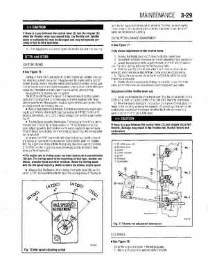
+ See Figure 76
Starting in 1988, the Suzuki digital ignition system was adoptedThis sysC tem eliminates direct mechanical linkage between the engine end the ignition systemInstead, sensors relay information detailing throttle position sensor, gear counter (engine speed) and engine temperature to the ignition module which processes this information and then determines the optimal ignition timingNo adjustment is necessary on this systemThe DT75 and DT85 use the Suzuki 1C (integrated circuit) ignition systemIgnition timing adjustment is not necessary on models equipped with these ignition systems with the exception of adjusting the throttle valve sensorThey are equipped with the following features: Engine Start Advance MechanismThis feature ensures easy engine starting by automatically advancing the ignition advance to 5OBTDC for about 15 seconds, after which, the 1C control circuit changes over to trolling ignition timingTrolling Speed Adjusting MechanismThe trolling ignition timing can be changed from 7OATDC in the slow position to 1°BTD by means of an idle speed adjusting switchEach position on the switch represents approximately 50 rpm changeBy changing over the trolling ignition timing, the trolling speed can be adjustedAll models from1991 have had the Idle Speed Adjustment Switch removed and instead an ignition timing resistor has been installedWith this modification, the in gear idle timing with the throttle fully returned is kept at constant 2O-6OATDC and the in-gear idle speed is now adjusted by the throttle stop screw on the #3 carburetor The engine rpm at trolling speed has been factory set at approximately 700 rpmThe trolling speed varies depending on boat type, weather conditions, propeller types and other variablesAdjust the trolling speed with the idle speed adjusting switch to obtain the desired engine speed1Remove the throttle lever rod (1) from the throttle control lever2Ensure that the throttle stop screw (on the #3 carburetor) if fully backed out3Loosen the screws (4) of the adjustable levers on the #I and #3 carburetorsThe return springs will close the throttle valves fully4Flick the lever (5) of the #2 carburetor or times, as shown by the arrow (A), which will ensure that all three throttle valves are closed evenly5Tighten the lever screws (4) on the #I and #3 carburetors and apply thread lock compound6Finally, check the operation by flicking the lever (5), see if the three to carburetor throttle valves are balanced and synchronized with each other Adjustment of the throttle lever rod1Adjust the dimension (B) of the throttle lever (1)to the correct lengthFor the DT75: 6.1 in(155 mm) and the DT85: 5.7 in(145 mm)Attach the control lever2Move the control lever (2) in the direction of the arrow (C) and adjust the length of the rod (1) by screwing the connector (7) accordinglyThe cam on the control lever should touch the stopper (6) when the throttle valves are fully open, or within lo-Z0of being fully openIf there is gap between the control lever (2) and stopper (6) at full throttle, damage may result to the throttle rod, throttle valves and carburetors1Throttle lever rod 2Control lever 3Lever 4Lever screws 5Lever 6Stopper 7connector