Suzuki outboard motors 1988 2003 repair manual., Page 39Get this manual
MAINTENANCE 3-23 7Turn the idle speed adjusting knob to adjust the idle speed to the specification listed in the "Tune-up Specifications chart The engine trolling speed has been factory adjusted to the optimum speedTrolling speed varies depending on boat type, weather conditions, propeller type and other variablesAdjustment can only be done with the engine in the water so there is back pressure against the exhaust systemIGNITION TIMING ISee Figures 67, 68 and 9
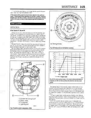
In these engines, 2-cylinder simultaneous ignition CDI system has been adoptedThe component parts of the ignition system are magneto and CDI unitThe CDI unit contains the ignition coilThe ignition timing characteristics are made up of the advance angle of the magneto itself and the advance angle of stator slidingAn electronic advance system employing 1C has been adopted in the advance angle of the magneto itself to assure highly precise ignition characteristicsThe CDI unit also includes the over-rev limiter and oil warning circuitThe total 27Oignition timing is the result of the combination of magneto and CDI unit that produces the 7OelectricaI advance angle shown in the illustration and the 20°advanc angle when the magneto stator slidesWhen the flywheel rotates, electromotive force is generated in the condenser charge coil and causes the current output from the positive side to flow from the condenser charge coil to the diode to the condenser to the ignition coil where it then charges the condenser charge coilNext, when the timing coil and the flywheel magneto pole piece position become opposed, output is generated in the timing coil, resulting in the current flow from the timing coil to the diode to the SCR gate to ground, causing the SCR to change over from OFF to ONATiming marks