Suzuki DF200/DF225/DF250 V6 4-Stroke Outboards Service Manual, Page 92Get this manual
ENGINE CONTROL SYSTEM
MULTI-STAGE INDUCTION
OUTLINE
The multi-stage induction system is designed to improve the intake efficiency by changing the intake tract volume in accordance with the engine speedThis system improves low and mid range torque and increases power output at the higher rpm ranges
SYSTEM COMPOSITION
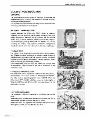
Located between the STBD and PORT banks, collector assembly provides air for the lowmid range intake tract and high speed range tractsMounted on the collector are two throttle bodies, VSV (Vacuum Switching Valve), vacuum tank, depression chamber for operating the system and the shut off valve for switching the intake tractSystem connection components include one check valve and hose to form the vacuum passage VACUUM TANK The vacuum tank stores vacuum created during engine operationThe vacuum tank' purpose is to supply stable vacuum to the depression chamber under the varying vacuum conditions normally occurring within the collector, thereby making it possible to control the shut off valve accuratelyA hose and check valve connects one side of the vacuum tank to the collectorThe other side of the tank is connected to the VSV with hose VSV (Vacuum switching valve) One side of the VSV is connected via hose to the vacuum tank, the other side is connected via hose to the depression chamberThe VSV receives operating signals from the ECMWhen the ECM signals OFF, the VSV releases vacuum to the atmosphereWhen the ECM signals ON, the VSV supplies vacuum to the depression chamber