Suzuki 90-200HP outboard motors Service Manual, Page 18Get this manual
SERVICE MANUAL attached to black cover over throttle valve sensor and insert alignment pin (1) into hole in sensor and sensor cam (;3)Align slot in cam (3) with throttle shaftDisconnect throttle valve sensor connector (4)Connect test harness 09930895:30 or suitable jumper wires to battery as shown in FigSZI7-11Battery voltage must be nine volts or moreConnect positive+) lead of suitable DIGITAL ,oltmeter to test harness light green wire with red tracer and voltmeter negative-lead to battery negative (-) terminal as shownWith throttle fully dosed, voltmeter reading should be 0.45-0.55 voltIf not, remove rubber cap (2) and turn adjustment screw (under cap) as necessary to obtain the correct voltage readingNote that turning aqjust.ment screw clockwise will increase voltage and counterclockwise will decrease voltageNOTE: The manufacturer recommends usIng only nonmetallic screwdriver to turn sensor adjusting screw or sensor voltmeter reading may not be validIf metal screw-
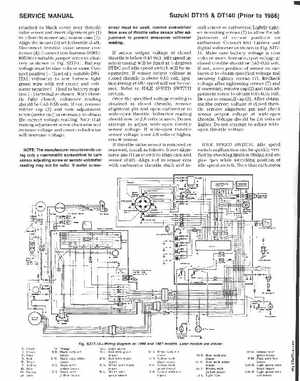
Suzuki OT11501140 (Prior to 1986)