Suzuki 90-200HP outboard motors Service Manual, Page 5Get this manual
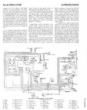
Suzuki DT90DT100 orange wires for numbe coil, black and blue wires for numhe coilblack nd gra)' lI'ires for numbe :3 coil and bla('k and !,'Teen wires for number coil SC'co ndary winding resistance should br 2fiOO-:3800 ohmsplus 10,000 ohms for he spark plug term ina capTest seco ndary resistan('e hy co nn ecting tester between th spark plu te rmin al and ora nge primary wire for number coil, blu primary wire for numlJer coilgray prinwt wire for Ilumbe coil and primary wi re for numbe coilIDLE SPEED ADJUSTING SWITCIIIdle speed adjustment switch is used to aCjust idle speed by ignition tim ingIdle speed switch failure ca qUickly verified hy conn"cling suitable timing light to Ih Slart ngine and allow to idle:.rote timing while changing posi ion of idl (' speed switch If tim ing dl)('s not Hl nge ith eac switch positiollidle speed switch is defective and shOU ld be rellewed To test idl speed wite-hdisconnect wires and conn ect ester het ween the two black: whit wiresHefer to FigSZHl-17shou ld be as follows: Position A-zero ohmposition n-18002()Ofl ohms; position C-5600-S200 ohms: position [)- lU,()OO-2:l.000 ohms; posi tion E-innnityTlIIIOTTLE SE:.rSO lt Th th rott le valve sensor provid es hrottle position information to the Mi cro Link ignition systemTh sensor is mounted on th port side of bottom carbure torDrive gear (5Fi gSZl !l- IS) engaged with carburetor hmttle shaft (:3) rotates driven gear (I) which tllrns he pot entiom et er shaftlh lest se nsor, disco nn ect wires leading from sensorConnect ohmnH't er bet ween ligh greenred wire and hlack wireWith hrotll ',llves comple tely